Department of Mechanical Engineering, Imperial College, London
Abstract
In 1912, Titanic, the largest ship afloat at the time collided with an iceberg and sank in the North Atlantic Ocean due to extensive damage to its hull. However, a fact well documented but often forgotten is that, from the moment the Titanic began her first sea trials and set sail to Southampton, coal in one of the ships’ bunkers was burning in a smouldering fire. Fire was adjacent to one of the watertight bulkheads. A new theory has been put forward recently in the 2017 documentary Titanic: The New Theory that the smouldering coal fire could have weakened the steel leading to the premature collapse of the bulkhead accelerating the sinking. Nevertheless, this is a new theory and this paper reports research to investigate it. A preliminary study of the structural response of a steel bulkhead similar to that in the Titanic exposed to the kind of localised heating produced by a smouldering coal fire is presented. Six case studies are investigated, varying the size of the heated area and peak temperature of the steel. Results indicate that several cases lead to similar deformation patterns as described by firemen in the Titanic. Moreover, we report high residual stresses in the bulkhead which could result in premature collapse when further loading is applied.
1. Introduction
Titanic, built in Belfast, was a passenger liner and the largest ship afloat at the time. The ship sank in 1912 in the North Atlantic Ocean on its way to New York City after hitting an iceberg and experiencing extensive damage to its hull1. However, it is little known that, from the moment the Titanic began her first sea trials and set sail to Southampton, coal in one of the ships’ bunkers was burning in a smouldering fire.2,3,4 Smouldering is the slow, low temperature, flameless burning of porous fuels.5 It is believed that the smouldering fire started by self-heating while the Titanic was still in Belfast. Route of the Titanic is illustrated in Figure 1.
Fire was detected in the coal bunker in Southampton 8 days (see Figure 1) after the sea trials had begun. It was located between boiler rooms #5 and #6 (see Figures 2 and 3). There was a watertight bulkhead running right through the centre of the bunker with coal on either side. Watertight bulkheads are vertical steel partitions that prevent ingress of water to adjacent compartments if the hull of the ship is damaged. Throughout the entire journey from Southampton, after detecting the fire, a crew of firemen was assigned to put out the fire by removing the coal from the bunker into the boilers or furnaces. Coal removal is the best way to deal with smouldering.5 Fire was spreading from one side of the bulkhead to the other through heat transfer. It is believed that 3 days after the detection of the fire (1 day before colliding with the iceberg), during the evening watch, firemen finished removing coal from one side of the affected bunker. Then some firemen observed deformations in the steel in the bulkhead. The Titanic Inquiry Project6 collected testimonies from the British Inquiry hearings, which took place between the 2nd of May and 3rd of July 1912, about this damage:
Leading Fireman Charles Hendrickson:
“You could see where it had been red hot; all the paint and everything was off. It was dented a bit.”, “Yes, warped.”
Leading Fireman Frederick Barrett:
“It was damaged from the bottom.”, “The bottom of the watertight compartment was dinged aft and the other part was dinged forward.”
Smouldering coal can reach peak temperatures up to 1000°C.5,7 In the Titanic, the fire affected the steel bulkhead. Steel exposed to such coal fire could reach temperatures between 500 and 800°C depending on cooling conditions on both sides of steel. Heated to such high temperatures steel loses 40% or more of its strength.8 In addition, steel used in the Titanic was weaker than modern steel.1,9 The steel used in the Titanic had large grain structure and higher sulphur and phosphorus concentrations than currently acceptable, resulting in a more brittle material than modern steel.1 After colliding with the iceberg, the bulkhead damaged by the fire was adjacent to one of the five breached and flooding with sea water watertight compartments (see Figure 2). In 2017, a new theory has been put forward in the documentary Titanic: The New Evidence3 that the weakened steel due to the intensity of the smouldering coal fire could have contributed to the premature collapse of the fire affected bulkhead due to water pressure. This, therefore, could have accelerated and marked the onset of the sinking of the ship. Nevertheless, this is a new theory and further research is necessary to investigate it.

(Google Maps)

(Original image: B. Lux, 1997)

(Background Image: Bill Sauder)
In the past few decades, there has been some work carried out to study various steel plates and sections exposed to high temperatures.10–14 Most of it has been carried out on steel plates subjected to uniform and localised heating 10,11 and uniformly heated webs and flanges of structural beam and column sections.12–14 In this paper, our preliminary study on the structural response of the Titanic’s steel watertight bulkhead subjected to localised heating is presented. To the best of the authors knowledge, no work has been conducted to date investigating the response of large watertight bulkheads subjected to fire. 6 different cases are investigated with varying assumed heated area and peak temperatures. Bulkhead deformation patterns and stresses are studied.
2. Computational Model
Watertight bulkheads in the Titanic were spanning the whole breadth of the ship (approx. 28 m) and were up to approx. 18 m high. We consider a representative section of the Titanic’s bulkhead with the area of 5 m by 7.3 m, which is illustrated in Figure 4. The bulkhead is assumed to be 2.5 cm (approx. 1 in) thick as in the Titanic 1 and have a continuous boundary condition representing the rest of the bulkhead. It is supported by a series of I-section stiffeners along one face. Their sections are assumed to be 0.1 m wide and 0.4 m or 0.8 m high. Density of steel of 7850 kg/m3 8, strength of 206.8 MPa 1, Young’s Modulus of 200 GPa 1, and Poisson’s ratio of 0.3 8 are assumed. For heat transfer and structural analyses at high temperatures, reduction factors for material properties are applied according to Eurocode 8. They are shown in Figures 5 and 6. It should be noted that this is only a preliminary study and many crude assumptions had to be made due to the lack and/or uncertainty of data on the construction of Titanic and material properties (especially at high temperatures) and for the sake of simplicity.
a) |
b) |
| Figure 4 — a) Illustration of the bulkhead used in the analyses; b) Front view of the bulkhead and illustration of the heated areas. |
|

a) |
b) |
| Figure 6 — Temperature dependent mechanical material properties of steel according to Eurocode 8 used in the computational model. |
|
2.1 Cases Investigated
Because the Titanic sank more than 100 years ago, there is too little evidence on the extent of the fire and its damage. Therefore, we perform a series of preliminary simulations varying the area of the heated patch. We assume it to be in direct contact with the burning coal and vary the temperature of steel. In total 6 different cases are selected. Two localised circular heating areas with the diameter, D, of 0.8 m or 2 m are considered (Fig. 4). For each of these cases peak temperatures of steel of 550°C and 1000°C are imposed. In addition, for the case with D = 2 m, two heating scenarios from different sides of the bulkhead are considered (i.e. Heating scenario B - front surface connected to the stiffeners, and Heating scenario A - back surface). A small thermal gradient through the bulkhead is assumed based on heat transfer analyses.
2.2 LS-DYNA Model
The steel bulkhead is modelled using the general-purpose finite element software LS-DYNA (Release 7.1.1) with an explicit solver. LS-DYNA can simulate the thermal, structural, and thermal-structural coupling problems. The software has been previously validated by the authors 16 against the available benchmarking and experimental data for structural fire analysis.
The bulkhead and stiffeners are modelled using the computationally robust and fast Belytschko-Tsay 17 shell element formulation with 2 through shell thickness integration points. The mesh size is 0.05 m. This was chosen as the optimal solution in terms of convergence and computational time based on the mesh density study. Due to symmetry, only half of the bulkhead is included in the domain. The bulkhead and the stiffeners are assumed to be rigidly connected and subjected to gravity load. A small arbitrary load of 30 N is applied to each node at the top of the bulkhead as well to represent some of the structural load and facilitate buckling. For heat transfer across the bulkhead and structural response analyses, thermally-sensitive (i.e. temperature dependent) material T10 and elastic-plastic material MAT 4 formulations, respectively, are used to represent the steel. Thermal load is applied directly to the shell elements over the heated area. It is unclear whether bulkhead was hot or cold during the sinking; therefore, cooling back to ambient temperature is also included in the model. During cooling, steel is assumed to regain its strength following a linear elastic unloading path.
3 Results and Discussion
3.1 Deflected Shape
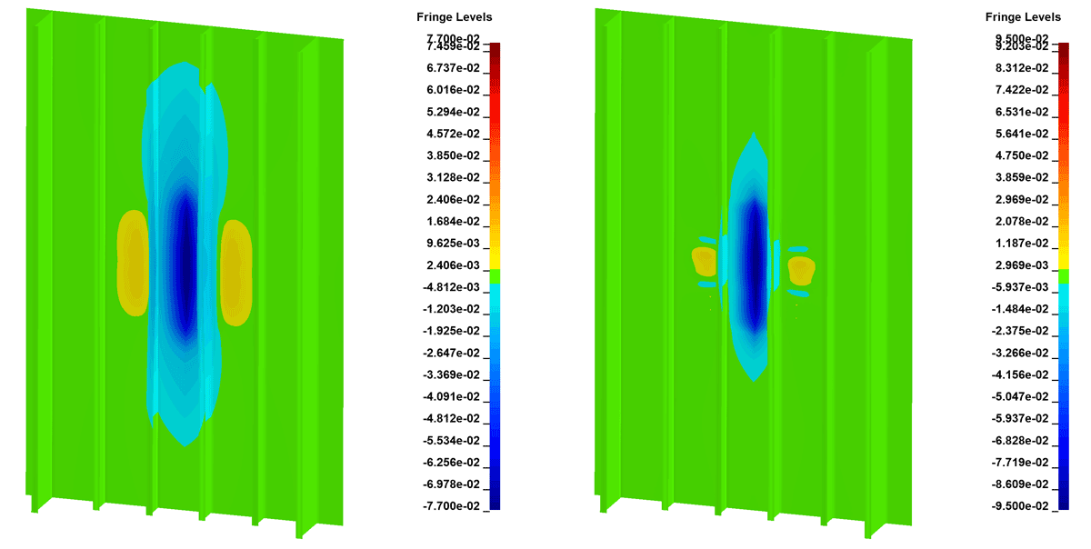
Figs. 7-9 show the deflected shape of the bulkhead at the maximum temperature (550°C or 1000°C) for all 6 cases. Fringe levels indicate out of plane displacement in m. Positive values indicate deformations towards the front (side where the stiffeners are located). Results indicate that as the heated area increases the extent of the plate over which deformations occur is significantly increased. In the heated area the bulkhead deforms towards the heat source. On the other hand, for the cases with the steel temperature of 1000°C the affected area appears to be more localised in comparison to the cases with the steel temperature of 550°C. This is counterintuitive and could likely be caused by yielding of steel during heating to 1000°C. At the temperature of 1000°C, steel maintains only 4% of its ambient temperature strength.
Comparison of the peak displacements and residual displacements after cooling along horizontal central axis of the bulkhead in the heated area is shown in Figure 10. After the coal was removed from one of the coal bunkers to eliminate the fire in the titanic, firemen observed deformations in the steel bulkhead defining it as “warped” and “dinged aft <…> and forward”. Similar deformation patterns in residual displacements (i.e. after cooling) can be observed for all of the cases (Figure 10), although, at the peak temperature this is not observed for the cases with D = 0.8 m. Though, magnitudes of residual displacements are relatively small ranging from -11 mm to 27 mm. Although, the extent of deformations in cases heated to 550°C is larger as identified previously, the magnitude of these deformations (both peak and residual) is significantly smaller in comparison to the other cases. For all scenarios peak displacements during the heating are the highest for the maximum temperature of 1000°C by up to 20 mm. Deformations are slightly higher (by approx. 10 mm) in the cases where stiffeners are heated as well.


3.2 Stresses
Both peak and residual displacement patterns shown in Fig. 8 indicate yielding of the bulkhead at the centre of the heated area either during the heating or cooling. Plate with the heated area diameter of 0.8 m appears to yield during the cooling due to formation of hinges close to the edge or centre of the heated area. Yielding of some shell elements in the heated area can also be observed in the change of longitudinal and transverse stresses across the bulkhead. Initially, stresses in the bulkhead increase with increasing steel temperature due to the restrained thermal expansion but once the bulkhead yields at specific locations or buckles, these stresses begin to decrease as they are redistributed to the surrounding stronger elements.
Peak stresses reached during the heating are within the same range irrespective of the fire scenario and are up to 190 MPa both in longitudinal and transverse directions. During cooling, once elements begin to regain their strength high residual stresses develop in all of the cases. In some cases residual stresses go up to 200 MPa irrespective of the maximum temperature of the heated area indicating significant utilization. This could be detrimental if any significant post fire load were to be applied (e.g. high water pressure) and could result in failure.
4. Conclusions
Recently, a new theory has been put forward in documentary Titanic: The New Theory that a smouldering coal fire in the Titanic could have weakened one od watertight bulkheads accelerating the sinking of the ship. In this paper, a preliminary study of the structural response of the Titanic’s steel bulkhead subjected to localised heating has been presented. Six different cases have been investigated with varying size of the heated area and its maximum temperature. Results indicate similar deformation patterns as indicated by firemen in the Titanic. However, their maximum amplitude is relatively small (up to 25 mm). Furthermore, results indicate that, irrespective of the fire scenario considered, localised heating in the bulkhead results in high residual stresses up to 200 MPa indicating high utilization (i.e. the bulkhead can sustain a smaller additional load than prior to the fire). Similarly, the coal fire in the Titanic could have weakened the watertight bulkhead (if the steel cooled down prior to collision) leading to a premature failure. However, it should be noted that this is only a preliminary simplified study and further more detailed and advanced parametric studies need to be carried out to confirm this, which is the aim of the authors.
References
- Hooper McCarty, J. and Foecke, T., What Really Sank the Titanic: New Forensic Discoveries. Citadel, 2008.
- TRMA, Coal Bunker Fire. [Online]. Available: http://titanic-model.com/db/db-03/CoalBunkerFire.htm. [Accessed: 07-Jul-2017].
- Taplin, S., Titanic: The New Evidence, Channel 4, UK, 2017.
- Essenhigh, R. H., What sank the titanic? Possible contribution of the bunker fire, 2004 Denver Annual Meeting (November 7-10). Geological Society of America Abstracts with Programs., 36, No. 5, 2004, p. 42.
- Rein, G., Smoldering Combustion, in SFPE Handbook of Fire Protection Engineering, New York, NY: Springer New York, 2016, pp. 581–603.
- Titanic Inquiry Project, Wreck Commissioner’s Inquiry. [Online]. Available: http://www.titanicinquiry.org/BOTInq/BOTIndx01.php. [Accessed: 07-Jul-2017].
- Hadden, R. and Rein, G., Burning and Water Suppression of Smoldering Coal Fires in Small-Scale Laboratory Experiments, in Coal and Peat Fires: A Global Perspective, Elsevier, 2011, pp. 317–326.
- CEN, EN 1993-1-2:2005 - Eurocode 3. Design of steel structures. General rules. Structural fire design. 2005.
- Hooper, J. J., Analysis of the Rivets from the RMS Titanic using Experimental and Theoretical Techniques, John Hopkins University, 2003.
- Guedes Soares, C., Gordo, J. M. and Teixeira, A. P., Elasto-Plastic Behaviour of Plates Subjected to Heat Loads, Journal of Constructional Steel Research, 45, No. 2, 1998, pp. 179–198.
- Guedes Soares, C. and Teixeira, A. P., Strength of plates subjected to localised heat loads, Journal of Constructional Steel Research, 53, No. 3, 2000, pp. 335–358.
- Couto, C., Vila Real, P., Lopes, N. and Zhao, B., Effective width method to account for the local buckling of steel thin plates at elevated temperatures, Thin-Walled Structures, 84, 2014, pp. 134–149.
- Selamet, S. and Garlock, M. E., Plate Buckling Strength of Steel Wide-Flange Sections at Elevated Temperatures, Journal of Structural Engineering, 139, No. 11, 2013, pp. 1853–1865.
- Knobloch, M. and Fontana, M., Strain-based approach to local buckling of steel sections subjected to fire, Journal of Constructional Steel Research, 62, No. 1–2, 2006, pp. 44–67.
- Komatina, M., Manovic, V. and Dakic, D., An Experimental Study of Temperature of Burning Coal Particle in Fluidized Bed, Energy & Fuels, 20, No. 1, 2006, pp. 114–119.
- Rackauskaite, E., Kotsovinos, P. and Rein, G., Model parameter sensitivity and benchmarking of the explicit dynamic solver of LS-DYNA for structural analysis in case of fire, Fire Safety Journal, 2017.
- LSTC, LS-DYNA Keyword User’s Manual, Volumes I to III (Version R7.1). Liwermore: Livermore Software Technology Corporation (LSTC), 2014.
Original Citation
E Rackauskaite and G Rein, The possible role of fire in the sinking of the Titanic - structural response of a steel bulkhead subjected to localised heating, 2017 ISO Fire Safety Conference, Santander, Spain. https://doi.org/10.5281/

Comment and discuss